Short Circuits
|
|
Short Circuits |
|
Don't be put off by the main title. It's not the circuits that are short, it's the articles.
This series of articles on model railway electrics was originally intended to be published in a monthly newsletter with the intention of giving an insight as to the many simple ways to get the most operational fun from your train set or if you take things a bit more seriously, model railway layout. The articles and associated diagrams are intended to demonstrate practical and inexpensive explanations to many of the electrical control situations encountered when designing the control system and wiring for your layout.
Of course this subject of model railway electrics has already been well documented in many commercially published books but these books all have one thing in common, they tend to very quickly become complex and full of a lot of inane and unnecessary technical theory and jargon. Be assured, this will not happen here.
IMPORTANT: The articles and wiring diagrams in this series pertain to two rail conventional analogue DC systems only and not to three rail DC, two or three rail AC nor to any aspect of Digital Command Control (DCC) systems.
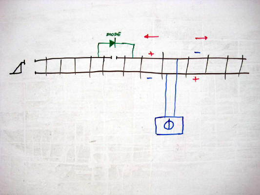
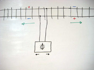
This may seem at first to be an odd question but there is a convention that has been used for more than sixty years concerning this very subject. Model railway manufacturers the world over have all adhered to this convention resulting in when you put your train on the track and turn on the controller, the train will proceed in one consistent direction.
The convention states that when the furthest away rail is more positive than the nearest rail, the train moves to your left. Reversing the controller makes the furthest away rail more negative than the nearer rail, therefore the train moves to the right.
If your train does not adhere to this convention, you have a faulty train. This error could be due to a number of reasons. If the loco is brand new then there is a manufacturing fault and it should be returned to the retailer as being not fit for purpose. However, on older pre owned models, common reasons are that the magnet has become reversed or that the wiring to the motor has been reconnected incorrectly. If directionally controlled headlights are installed, it is important to ascertain whether the headlights and travel direction are in synchronisation. Reversing the wiring to the motor or lighting will remedy the problem.
Why is direction important? You really want all your trains to run the correct way for ease of operation in running, shunting and is of course it is absolutely essential for double heading or banking purposes. Also, as we shall see later in the Short Circuits series, control circuits utilising diodes will not work as intended on reverse wired locos. Don't end up going backwards. It's easy and it's worthwhile to get your direction correct.
When connecting the two power leads to the track, the most convenient way to do this is by means of a power connector or power clip. It is recommended that an analogue type is used as this contains a suppressor intended to reduce any interference to other wireless type apparatus. A power clip for use with digital systems does not contain this suppressor as it would corrupt the digital command signals.
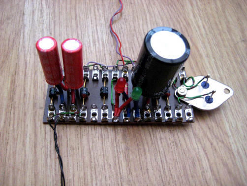
Almost everyone who has a model railway has a mains powered electrical device to make their trains run. They may refer to this device as a transformer, a controller, a line controller, a throttle or even a power unit. Whilst all these terms are generally accepted, there is really a little bit more to it than that.
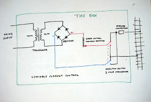
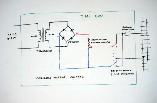
These devices consist fundamentally of five essential and discrete components within the box. These components are, a transformer, a rectifier, a user variable speed setting device, a direction switch and an overload protection device. There are two principal types of unit, ones with variable current control and ones with variable voltage control. Both types are in common usage today. A third, less common type of unit is also available called a Feedback Controller. These are not recommended for use with certain types of electric motors used in locomotives. Check the motor manufacturer's specification for compatibility before using this type of line controller.
So how do you tell the difference then? Connect the unit as usual making sure the controller is at stop and there are no trains on the track. Connect a test meter set to measure about 30 volts DC across the track. The reading should be zero. Turn the controller just off stop and observe the voltage reading. If the reading goes negative, reverse the test leads. If it immediately goes to about 20 or so volts, it is a variable current unit. If the volt meter reading increases proportionally with the speed setting, it is a variable voltage unit.
Variable current devices have been more common in the past and these rely on the value of the series connected variable resistance being compatible with the impedance or resistance of the motor in the train. Some units have a high/low resistance switch, some have a full/half wave switch and some even have both and if set correctly, performance will be noticeably improved.
Variable voltage units give a more responsive performance on a much greater range of motors from early Hornby Dublo and Tri-ang types up to the more efficient low current motors of today. The two diagrams illustrate the principal of the fundamental difference between the two types of units. Some voltage controllers have a variable multi tapping on the secondary windings of the transformer whilst both may use semiconductor circuitry to regulate the speed.
Which type is best? The answer to that is really down to what you think it is worth spending on probably the most essential accessory item you will ever purchase for your train set, the quality of the control that you require and also what the unit will deliver. It is essential that you try any new unit before you buy. A good new unit will cost you at least the price of yet another new locomotive. The choice is all yours but remember, without a quality control unit, none of you trains will run at their optimum performance.
Connecting to set track type track requires two wires and a power clip specified for analogue (not DCC) use. These power clips are fitted with a radio and TV suppressor or capacitor which helps to reduce reception interference on these devices. Power clips designated for DCC do not have the suppressor as it corrupts the digital control signals.
Next time you operate the train speed control you will know just what is happening within the box.
| Variable Current Control | Variable Voltage Control |
|
|
|
One of the features promoted for digital command control systems is the ability to independently control more than one train on the same section of track. To allow this facility to function requires lots of quite expensive and sophisticated technology. However it is possible to independently operate more than one train on a single section of track without having to resort to any complicated electrics or electronics.
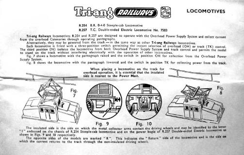
One of the first major manufacturers to exploit this dual train facility in 00 scale was the aptly named Trix-Twin system. The main drawback to their system was that their own special track was required which had an extra centre insulated third rail which was not readily compatible with other manufacturers track. In fact Trix-Twin even exceeded their own expectations by becoming Trix-Triple, introducing their own catenary system thus allowing no less than three trains to be independently controlled on one section of track. On most real electric railways though, power is usually supplied by an outside third rail or overhead catenary and returned trough the running rails. It is the latter that Tri-ang Railways introduced in the 1960's.
Tri-ang overhead electric locomotives were equipped with fully functioning pantographs connected to a three position selector switch allowing you to collect power from the track, a neutral centre off or overhead catenary. Power was returned via the other common running rail as usual. The clever bit is how this facility was promoted and kept simple. Tri-ang used the term "Hi/Lo Dual Control" for this feature and stated that no complicated electrics or modified locomotives were required. Remember that in this era, toy or model trains were intended for a young clientele to play with and enjoy, not like the situation today where everything is obsessively scrutinised by self appointed so called experts and over opinionated mature gentlemen and the model railway hobby is taken far too seriously.
So how did Hi/Lo Dual Control work then? Very well indeed. The dual train facility exploited the principal of what is known common return. Don't panic! This subject will be dealt with in a subsequent article. What is required are two locomotives, at least one of which of course has to be an overhead electric locomotive and two line controllers. It is absolutely imperative that these two line controllers derive their input from independent supplies. One line controller is connected to the track in the normal manner and the other is connected, one wire to the common return rail and the other to the power feed mast on the catenary system. There is no difficulty having two electric locomotives on the line as long as one is switched to the track and the other is switched to overhead. However, the one working on the overhead must be orientated the correct way round. There is a little "R" indicating return or common on the bogie frame to assist in identifying this. If you study the associated Tri-ang Railways wiring instructions you will see just how simple the whole system is to set up and play with. Anyway, it's much easier than reading through this article again.
|
|
|
Common return in electrical circuits is really more common that you may have thought. After all, Planet Earth is by far the largest common return conductor of all and it does seem to work rather well.
On model railway layouts it is an ideal way to reduce the number of interconnecting wires required between the control panel and your layout. In theory the minimum number of interconnecting wires may be defined as one wire per individual device or track section you wish to control or two wires to each point motor plus one and one only single common return wire. Even point control, whether it is solenoid or motor driven, can be reduced to one wire plus a common return. Using route control for points will also substantially reduce the amount of wiring too. More detail of those subjects though in subsequent articles.
However common return does have an inherent downside especially for the complacent and the unwary. As the sum of all the return current of all the circuits is passing along this one single conductor, it is absolutely essential that this conductor wire is of as low a resistance as possible. Using heavy gauge wire such as solid copper mains earth return wire is one solution to reducing this resistance. It is essential that all devices connected to this earth common are terminated with secure connections. This is not the place to have sloppy and twisted dry joints, bare wire connections or poorly terminated and soldered joints. Bad, resistive or even broken connections result in some really bizarre effects and can be time consuming to localise and fix. Not the situation you want to find yourself in within an exhibition environment.
Common return may be used for positive and negative earth common DC and also AC feeds to different devices and also for train control to track sections simultaneously. It is imperative, nay mandatory that every power supply connected to this common return is derived from a fully independent secondary transformer source.
There you are, you have almost halved the amount of wiring you have to install on your layout. Can't be all bad, can it?
Most people today that are interested in model railways started out as a child with the humble train set. Just which manufactures' train set you received depended on the era when you started out and of course the finances available.
The first readily available 00 scale train sets were produced by Hornby Dublo from 1938 onwards but this was a three rail system. The Hornby Dublo three rail range was not fully developed until the late 1940's due to Adolf interfering with the production schedule. The first readily available and mass marketed two rail system was produced by Tri-ang Railways around 1951. It took Hornby Dublo until 1958 to introduce a two rail system. Here endeth the history sermon.
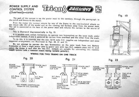
Once you have your trains running around an oval track, the first additions usually acquired is more track and some points. With the Tri-ang system there was only one rule concerning where the power feed was connected to the track. To ensure that either track was live depending on the setting of the point the feed must be at the toe (narrow) end of the point. All points are self isolating resulting in the point acting just like a change over switch.
If points are to be arranged with the power being fed from the heel of the point such as in a goods yard, all that is required is a single permanent bridging wire to maintain the fully operation self isolating facility. Rail gapping and additional power feeds are not necessary. Everything about two rail track layouts remained nice and simple until Hornby Dublo introduced their own version of two rail.
The fundamental difference between Tri-ang and Dublo two rail track was the points. Tri-ang used self isolating dead frog points and Dublo used self isolating live frog points. As anyone who has built a Dublo two rail layout will know, Dublo two rail track geometry is very convoluted and with it is the added complication of essential double and single rail gapping even for an oval with just one single point. Not a simple matter by any means. Dublo produced copious amounts of instruction concerning these complications but in reality, who reads instructions, especially on Christmas day?
Don't be put off by live frog points. They permit an improved quality of running and also better reliability. Using, wiring and gapping live frog points is not complicated but the rules must be adhered to. That's for next time.
| Dead or Insulfrog Point. Link wire. No gap required. | Live or Electrofrog Point. Link wire. Gap essential. |
|
|
|
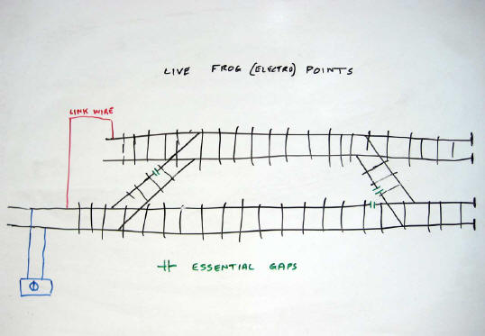
Many people are discouraged from using live frog points by the misconstrued idea that the wiring for the track is very complicated. Scrutinising commercial publications such as "How to wire your layout" and "Electrics for Model Railways", you would indeed be led assume that this is the case. Time to dispel that myth once and for all.
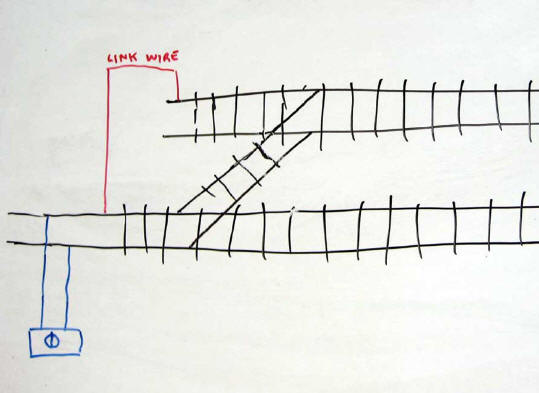
Unlike dead frog points where insulated rail gaps are not normally essential, live frog points and associated track do require a bit of forethought before finally pinning everything down. Much of the wiring illustrated in the commercial instruction books may be eliminated quite simply by the use of strategically placed insulated single rail gaps without losing any of the operational functionality.
The general rule is that if the track feed is towards of the toe of the live frog point, no gaps are required. However if the power feed is towards the heel end then gaps are essential to avoid the possibilities of short circuits. Once these insulated gaps are installed, you can forget all about them. There is also no need for any additional wiring or switching.
Once again it is much easier to understand the principals of wiring using live frog points by looking at the diagrams. Remember that with live frog points the frog is permanently connected to its adjacent running rails at all times, therefore the polarity of these rails is dependent on the setting of the point, not on whether it is the furthest or nearest away rail. The diagrams will explain this much more simply than text ever can. Don't despair, keep it live.
| Dead or Insulfrog Points | Live or Electrofrog Points |
|
|
|
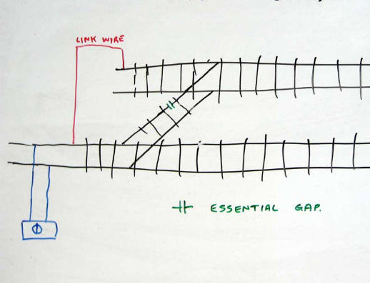
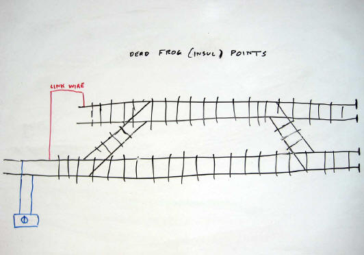
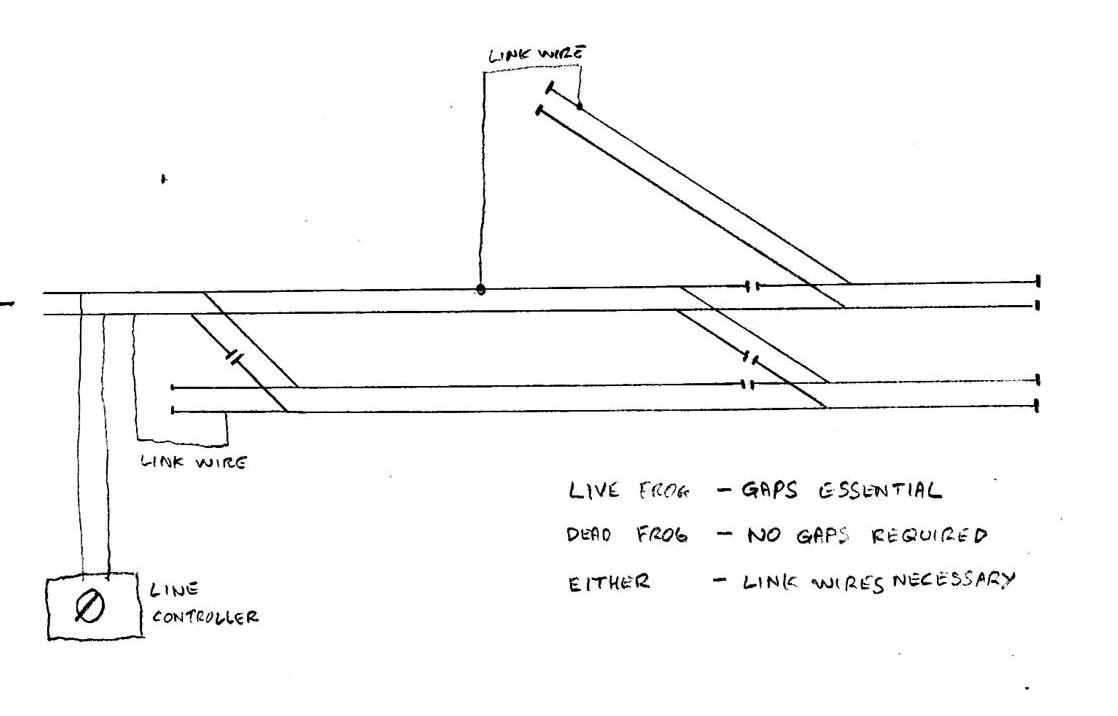
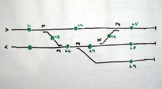
The example below shows the general principal of where and when gaps and link wires are required. The track layout is roughly based on the present day layout at Llangollen. All points, either dead or alive retain their self isolating feature. No switched extra power feeds are necessary. No gaps are required for the dead frog version but are essential for the live frog one. The two link wires are required for both versions. Simples!
Now we have the trains running properly and the points installed it is time to think about being able to control the points (track switches) remotely. The simplest way is using the well proven wire in tube method and on some layouts this method of control is perfectly adequate. However if your layout is a bit larger then we really need something a bit more convenient for you to operate all your points.
As is usually the case, there is no single correct or best way to achieve remote point operation. There is the choice of solenoid or motor driven systems.
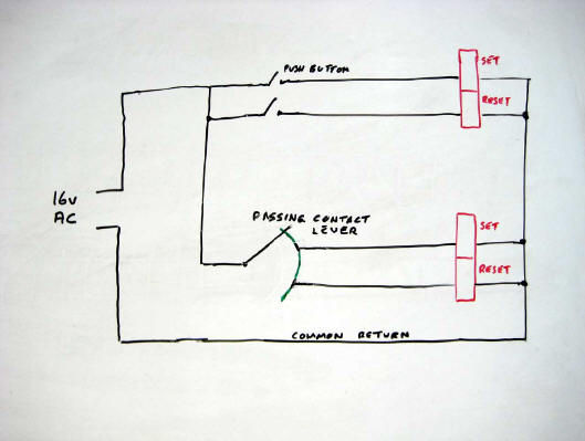
Normally for solenoid operation three wires are requited from a passing contact lever switch or two push buttons to each point. If you have read the article about common return you will know that this can be reduced to two wires plus one common return for all the points on your layout. The wiring may even be reduced to one wire to each point plus one common return but this involves a little more financial expense as a capacitor and a change over switch, not a passing contact switch are requires. As usual, the diagrams will explain the principal much more clearly than text ever can.
| Lever Switch
or Push Button Point Operation. Two wires plus common to each point. |
Single
Changeover Switch Point Operation. One wire plus common to each point. |
|
|
|
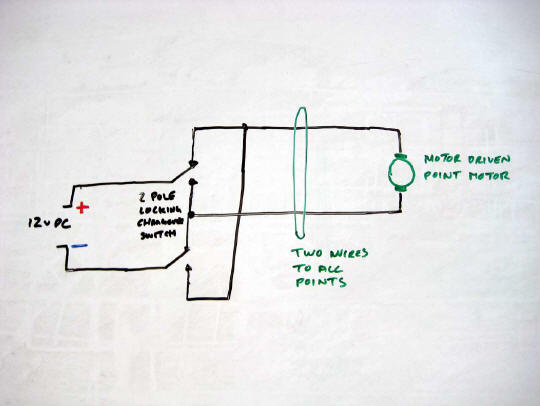
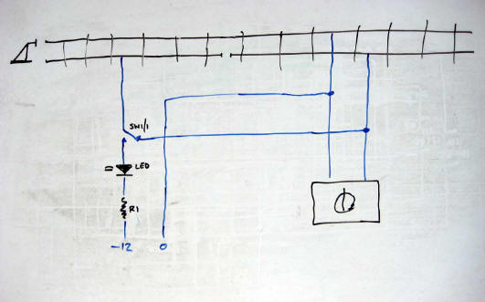
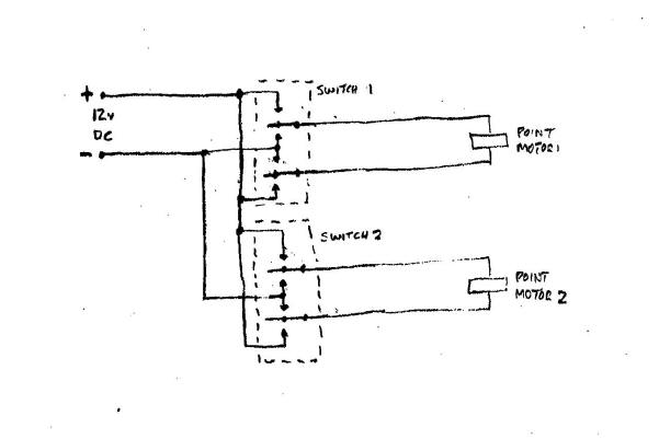
Motor driven point changing systems normally require two wires to each point. Power is fed via a two pole change over switch which reverses the polarity across the motor, operating the motor in the reverse direction and changing the point. All that is required is a supply of 12 volts DC and one switch for each point. The diagram explains all.
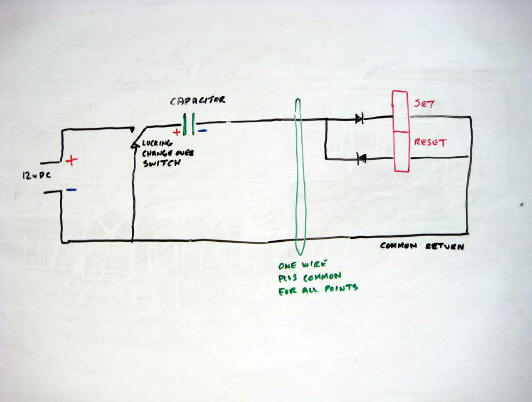
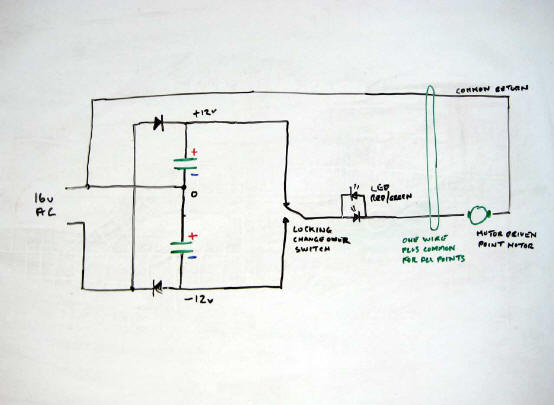
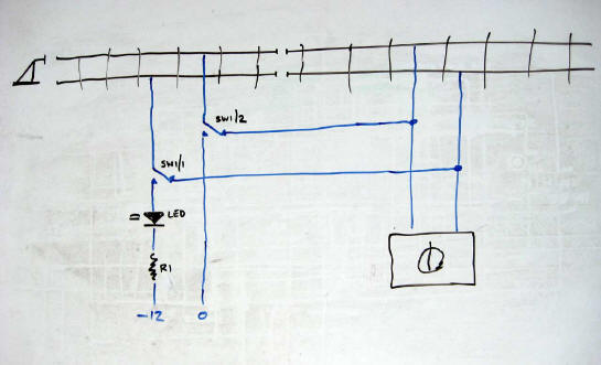
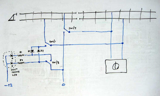
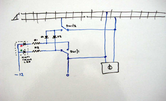
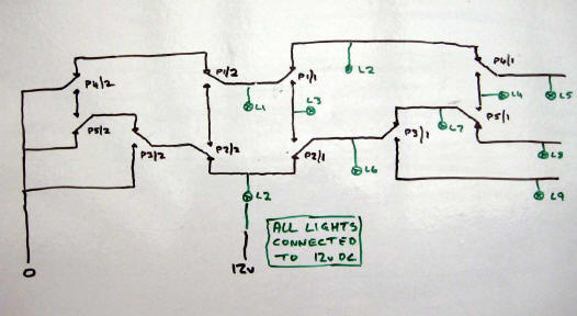
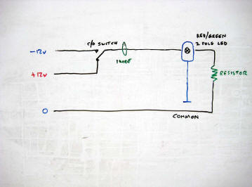
Don't despair, there is a much more economical way in wiring to do this using that great savior of us all, namely common return. First we need a power supply of +12 and -12 volts DC relative to a common earth. This can be derived from a single 16 volt AC source with the aid of two diodes and two capacitors. Once again the diagram is much easier to comprehend that the text. To control each point, this time only a single pole change over locking switch is required. One terminal of the point motor is connected to the common earth and the other to the centre of the change over switch. The other two terminals on the switch are connected to the +12 and -12 volt supply. Operating the switch changes the polarity of the connecting wire from positive to negative and the motor reverses. Just look at the diagram, it's easier.
As a bonus, if you connect a bi-polar (red/green) two leg LED in series with the control wire to the motor, in this case no resistor is required as the point motor substitutes for the resistor, you will get an indication of which way the point is set. Simples!
| Motor Driven Point. Two wires per point. | Motor Driven Point. One wire plus common per point. |
|
|
|
Routing systems for a layout makes operation much more straightforward and less easy to set thing wrong. If you have noticed, in a real mechanical interlocking signal box, the signalman requires considerable skill and experience to route the trains safely through his domain.
With the arrival of electro mechanical interlocking and before computers, the task became a bit more intuitive. One common system used was referred to as an NX (entrance exit) panel. Here you press switches along the route you wish the train to go. If the route is free of conflicts, the route and the appropriate signals will be set and locked until the passage of the train or the routing is cancelled. This is possible on a model railway but requires rather a lot of complicated wiring and many relay interlocking circuits.
There is a much simpler way of achieving a routing system for model railways as long as you are willing to accept the absence of any form of interlocking and inter linked automatic signalling systems. Non locking push to make switches can be located where routes divide or merge and on operation of the correct switch a group of point can be set in the appropriate position. There is no generic format for this, each layout has to be custom designed for the track layout. Limitations are the power of the capacitor discharge unit but the correct type can be made to operate up to six or more Peco type point motors simultaneously. Using common return from the point motors reduces the amount of wiring considerably.
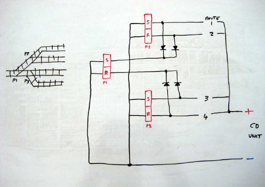
To understand this routing system, a wiring diagram absolutely essential. Draw all your point motors showing the set and reset connections. Plan where the routing switches are to be located and installed in geographic position on the control panel. One side of all the routing switches is connected to the positive of the capacitor discharge unit. The common of all the point motors is connected to the negative of the capacitor discharge unit. Now comes the fun bit.
Starting with the first route, on the diagram draw the wire to the points you wish to set or reset. Do this for all routes until you come to a point motor with a wire already on the terminal you wish to connect to. In this situation two diodes are required at the point motor to prevent feedback to other routes. If you follow the logic of the routed wires it does make sense.
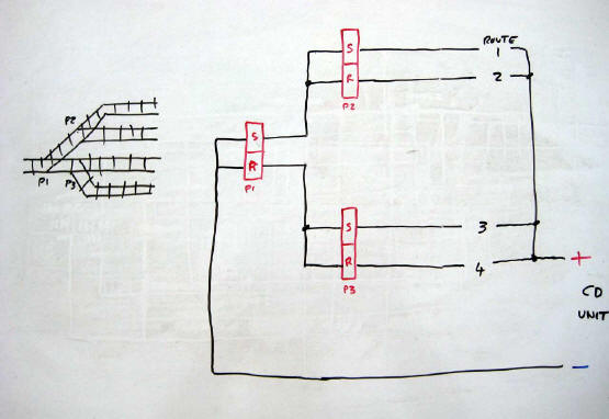
Alternatively if you have for example four routes converging into one, it is possible to wire the point motors in series as long as the capacitor discharge unit has adequate power. No diodes are required in this situation.
| Parallel connection. Diodes required. | Series connection. No diodes required |
|
|
|
You see switches advertised with numerous descriptions such as single pole single throw (SPST) and double pole double throw (DPDT). Do you understand what all this jargon actually means? If so then there is no benefit in you reading on. If not then please continue.
Switches are used to connect or disconnect a circuit or to divert a circuit from one location to another. Is important to use the right switch for the right function. The simplest function is to switch on and off a circuit and this requires a single make contact unit described as Single Pole Single Throw (SPST). There are two versions of this switch, locking or non locking. Locking stays on until you switch it off (used for isolating sections or station lights) and non locking (used for operating point solenoids) which returns to the previous setting on removal of your finger from the switch. If you add another contact unit or pole to the switch to independently switch another circuit this becomes Double Pole Single Throw (DPST). Also available are triple and quadruple pole switches.
Change over switches do just that. This time a centre contact switches between two different circuits. These are also available in multi pole options, for example if there are two change over units it is a Double Pole Double Throw Changeover (DPDT C/O). Also available in non locking format. Another option here is to have a centre off position and this becomes a Double Pole Double Throw Centre Off (DPDT C/Off). Also available is non locking in either one position or both positions. Uses for the first option is changing a point and connecting a track feed and the second is to set and reset a point solenoid.
Something else to remember is the voltage and current rating of a switch. Switching on but more so, switching off a higher current will cause arcing within the switch and will burn the switch contacts, especially if the item being disconnected is inductive such as a point solenoid. Use a switch rated for the job intended.
As always it is best to handle the switch before you buy. That way you will see the functionality (locking or non locking), see how many poles are installed and check the current and voltage ratings.
Yes, buying model railway electrical components is not as glamorous as buying a new locomotive or some new scenic items but if you want reliable operation of your layout there is only one option. Buying cheap is just that. It is false economy. It is always best to use good quality switches as that way you will only have to do your electrical wiring job once.
When Hornby Dublo introduced their 00 scale three rail system, one of the features exploited on their recommended layouts was the simple ability to reverse the direction of a train without the involvement of electrical switching, only track. Remember with this system, forward is always forward on the line controller. If you pick up and turn around a locomotive and then reapply power in the same direction, the locomotive will run in the opposite direction to before, in fact just as DCC systems do now.
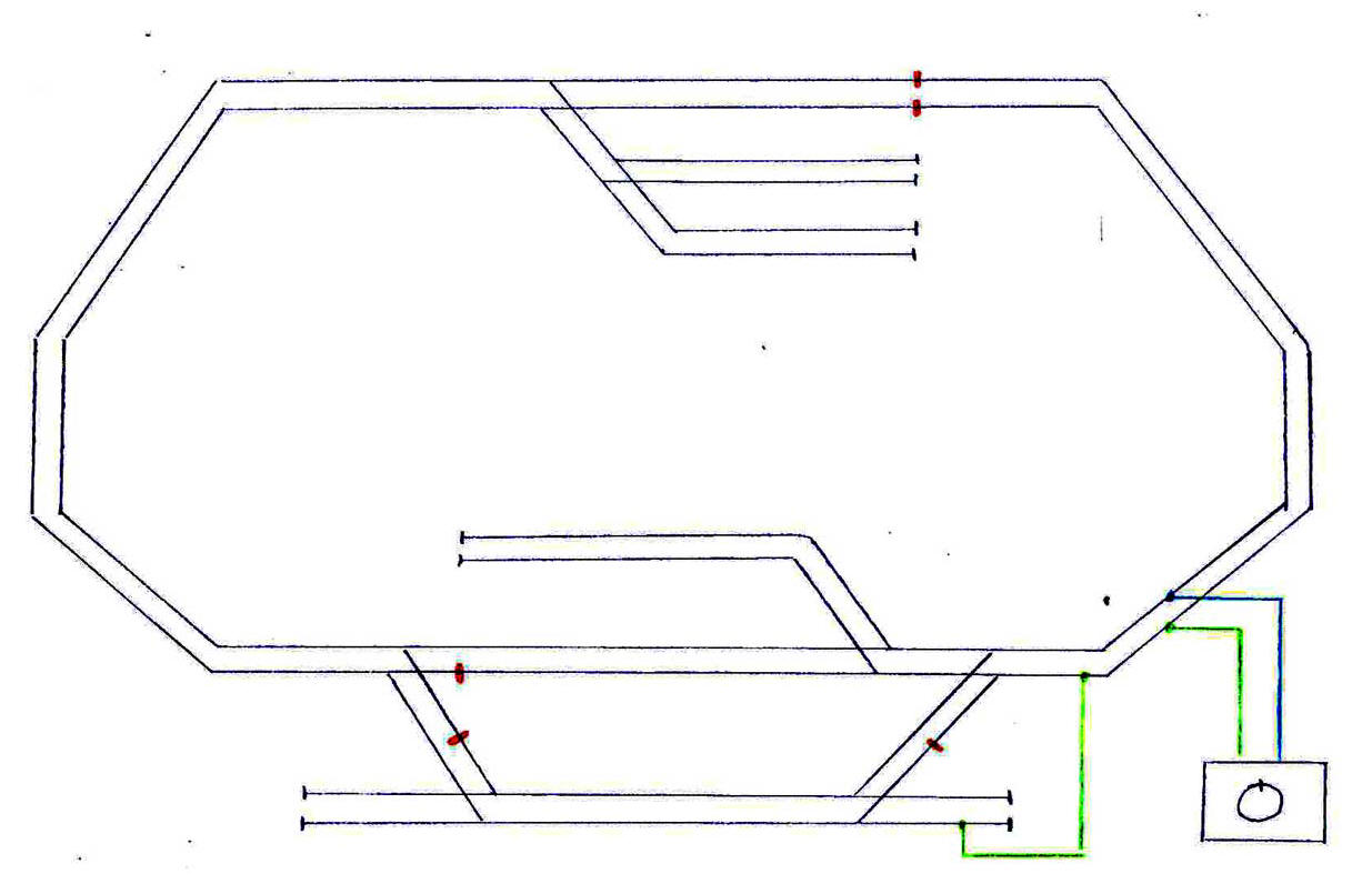
It is quite possible to have reversing loops on two rail layouts but it does require the use of correctly located single rail gaps and a bit of wiring. The first one requires one point, dead or alive and a turn back loop. Attached to the point a single changeover accessory switch requires to be fitted. Trains may be run around the loop in either direction depending on the setting of the point but must be stopped in the turn back loop for the point to be changed and the direction switch on the line controller to be reversed. Gaps should be located as shown and the three wires installed as on the diagram.
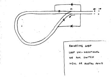
That's not the only way to do it. If you only have set track points, again dead or alive, without the facility of fitting an accessory switch, don't despair, there is a solution. Once again the gaps are located as shown but this time across each gap is fitted a diode, installed in the direction as shown. This solid state device conducts electricity in one direction only. As diodes are directional the slight drawback to this system is that trains can only be run around the turn back loop in one direction only. As a plus though, no wiring is required. Because of the use of diodes, it is imperative that your locomotives operate in the correct direction as mentioned in Short Circuits No. 1.
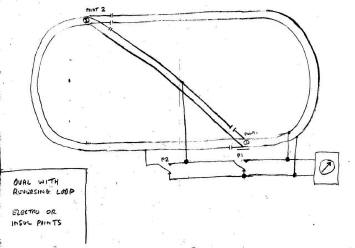
The third option shows a reversing loop installed in a traditional oval continuous run layout. With the wiring shown, the reversing loop can be used but it is required that the train is stopped in the cross loop whilst the relevant points are changed and the direction switch on the line controller is reversed.
There you are, three ways to turn back.
| Reversing
Loop. Auxiliary Switch. Bi-directional. |
Reversing
Loop. Diodes. Unidirectional. |
Reversing
Loop. Auxiliary switches. Bi-directional. |
 |
 |
 |
In forthcoming articles we shall be requiring some electrical or electronic accessories to use in our control circuits. These components are resistors, capacitors, diodes and relays. There is no need here to explain how or why they work, just what we can be use them for. If you want to know all the theory, there are many locations on the internet which will explain all in great detail.
One of the more common devices we use are resistors. By the name you can probably deduce that their purpose is to resist the flow of current. Resistors come in a wide range of values, the unit of resistance being the Ohm and also a wide range of power ratings, the unit being the Watt. Both values are important when using resistors. Resistors values and ratings can usually be identified by coloured bands around them. If you are lucky though the value may be printed on as numerals instead. The resistor colour code may be remembered by the use of an extremely politically incorrect rhyme which will absolutely not be reproduced here for fear of litigation. Ask anyone working in the electronics industry, they will be able to tell you.
Another component which is most useful in model railway electrics is the diode. Put simply, this device conducts current in one direction but not in the other. There are of course many different types of diode. For our uses we really want ones rated at about two amps forward current and about thirty volts peak inverse voltage in the non conducting direction.
A derivative of diodes that are most useful to us is the diode that lights up when passing current. They are of course called light emitting diodes. It is critical that they are operated at the current specified and are protected from excessive inverse voltages.
Capacitors charge up to the voltage connected across them and will retain this charge for a short time when this voltage is disconnected. For model railways electrics they are most commonly used in power supplies for solenoid operated point motors when a large amount of energy is required for a very short period. Larger electrolytic capacitors are polarity dependent and must be connected accordingly.
Relays can be considered as electrically operated switches and are useful for controlling train routing and interlocking colour light signals.
As with all electrical devices or even any kind of machinery, it is imperative that you do not operate the devices beyond their stated tolerances. Failure to adhere to this advice would be stupid and dangerous and possibly result in personal injury, overheating and fire.
Whilst it is perfectly adequate to power your solenoid operated points directly from a 12 volt DC or 16 volt AC supply, there are a couple of limitations that show up. The supply will only usually change one point at a time and if the lever switch or push button is held operated for any length of time there is the problem of overheating, much melting of plastic and windings, all accompanied by an acrid burning smell. There must be a better way of doing it. There is. It is called a Capacitor Discharge Unit or CD Unit.
A good analogy to a model railway capacitor discharge unit is the lavatory cistern. Here a small bore pipe delivers water at a limited rate of flow and fills or charges up the cistern. On operation of the flush mechanism, a large amount of water discharges rapidly, executing its primary function.
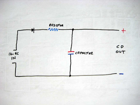
For the simplest form of model railway CD unit all that is required is a capacitor and a resistor. When power is connected the capacitor charges via the resistor up to the peak value, not the average value, of the supply, usually about 22 volts. On operation of a point button or switch the energy stored in the capacitor operates the solenoid. If the button is held operated, the current through the solenoid is limited by the value of the resistor thus preventing the melting solenoid syndrome. The advantage of using an AC supply is the higher peak voltage as the energy stored in a capacitor is proportional to its capacitance but is proportional to the square of the voltage. With this simple unit there is one downside however, because of the resistor, the unit will take time to recharge, just like the water cistern.
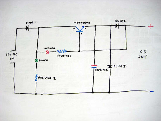
The solution to much reducing the time delay is to venture into solid state technology using a power transistor. The transistor is used as a switch to disconnect the output if any buttons are held operated. On release of the button the capacitor charges directly from the supply and is ready for use very quickly. The green LED indicated power is on and the red LED indicates a button held in the operating position. On disconnection of the power supply the unit will automatically self discharge saving you the treat of getting a surprise bite from the capacitor. Commercial purchased units may be limited in the number of points that can be changed simultaneously therefore a custom built version can be made to provide extra energy.
Buying the few components is not expensive and remember you only have to build one of them for your whole layout.
Do you want to change even more points simultaneously? That's for next time.
| Simple Capacitor Discharge Unit | Fast Recovery Capacitor Discharge Unit |
|
|
|
As mentioned in the previous article, the energy stored in a capacitor is proportional to the value of the capacitance and also proportional to the square of the voltage supply. To coax more energy from a CD unit there are two possibilities. One is to increase the value of the capacitor and the other is to increase the operating voltage.
Increasing the capacitance requires larger and more expensive capacitors but increasing the supply voltage is relatively inexpensive. Be warned though, before doing this make sure all the components are suitably rated for the increased voltage. Do not operate any components beyond their recommended safe tolerances. Doubling the voltage results in four times the energy in the capacitor.
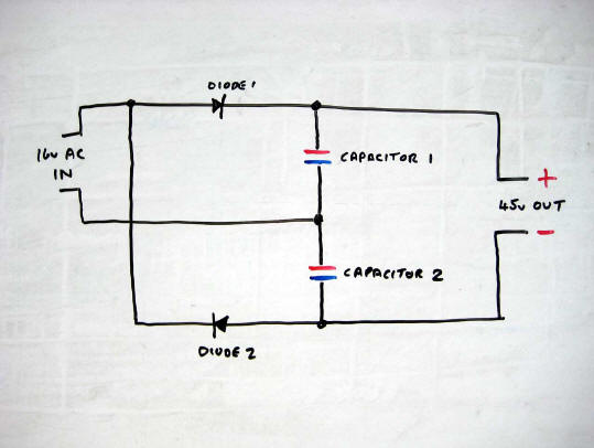
Usually the only power supply available on model railway layouts is either 12 volts DC or 16 volts AC. For this voltage booster we use a modified version of the +12 and -12 volt power supply unit as used previously. To be absolutely clear, the voltage difference between +12 and -12 is of course 24 volts.
It is essential to use a 16 volt AC supply as the two capacitors are charged up on the alternating cycles of the AC supply. Again the capacitors charge up to the peak value, not the average value, of the supply, about 22 volts. This give an output of about 44 volts DC. This supply is connected to the input of the CD unit and gives an output of about 44 volts with four times the energy of the 22 volt version.
Is this higher voltage safe in a model railway environment? Indeed it is. Because the transistor switches off very quickly the solenoids can not be overloaded. The higher voltage is quite safe as the energy is delivered for a very short time only. Touching the terminals will cause no real sensation unless your hands and body are very wet and you are standing naked in a half filled bath. You wouldn't want to be doing that, now would you?
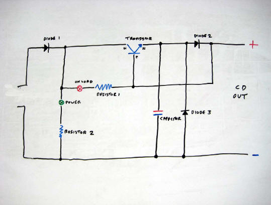
| Voltage Boosting Circuit | Fast Recovery Higher Energy Capacitor Discharge Unit |
|
|
|
|
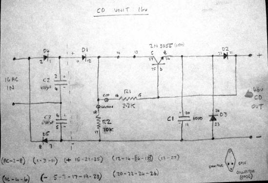
Wiring diagram for high energy Capacitor Discharge unit |
The completed high energy Capacitor Discharge unit |
|
|
|
As mentioned in previous articles, diodes are really useful devices in model railway control circuits. Fundamentally, a diode is a solid state device that passes current in one direction only with only a very slight voltage drop. In the reverse direction a very high resistance is presented so no current flows. So what can we use them for?
Do you have dead end sidings on your layout and have you ever driven a train off the end of the siding, crashing into the buffers or even worse, crashing through the buffers and off the layout and onto the floor thus ending in financial tragedy. If the answer to that question is yes then this is for you.
By having a single rail gap bridged by a diode correctly connected, an automatic dead section of a couple of feet may be inserted. Once the loco passes the gap, current is disconnected and the loco stops, somewhat abruptly but that is preferential to it ending up on the floor. To retrieve the loco from the siding simply reverse the line controller and the loco can be reversed out. This only works of course if the loco is at its traditional place at the front of the train.
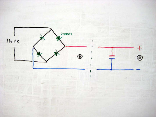
Diodes grouped in fours can be used a rectifier, that is to convert from Alternating Current AC to Direct Current DC. Units are available with the four diodes encased in plastic and is much more convenient to use. The output from this rectifier is unsmooth DC at about 14 volts at position A. If a capacitor is connected as shown this will smooth out the output and also increase the output voltage due to the capacitor charging up to the peak value of the AC supply at position B. As always, make sure all the components are operated within their stated tolerances.
Single diodes are also useful if headlights on locos are required to operate in one direction only. Just wire a diode in series with the lamp. If using LED lights make sure that reverse voltages are not connected across them. Use a regular diode in series with the LED.
Self flashing LED lights are available. If further regular LED lights are connected in series with one then all the LED lights in the circuit will flash, not just the flashing one. The uses are infinite.
| Automatic stop at the end of a siding. | Diodes used as a rectifier. |
|
|
|
Signalling on model railways can become rather an involved process. Although scenery, trains and signals can be reduced in scale, the means to control signals can not. To provide accurate signalling on your layout requires almost as much circuitry as the real thing. Don't despair though, reasonably simple, representative operational signalling can be installed so long as you are willing to accept a few compromises.
Semaphore signals can be operated by wire in tube, solenoids or even motor driven systems with control circuitry similar to point switching. Colour light signals do have more scope for different methods of control. As always there is no one single correct method, just different ways of achieving similar results. With signalling on real railways, much of the complex circuitry is for the interlocking of points and signals to ensure safety and to prevent the signalman from setting up conflicting routes. If you want to replicate this accurately, the same circuitry employed by Network Rail would be required for your layout. A somewhat daunting task. If you are prepared to accept compromises on not having a foolproof system then read on.
Point or turnout control as already been covered in previous articles so now its the various simple ways to control colour light signals. Once again common return is used to reduce on wiring. There are two fundamental types of colour light signals, ones with separate colour aspects with either two, three or four lamps and single lens searchlight signals that can indicate either red, yellow or green but only one at a time of course.
Model signals can use either lamps or light emitting diodes. Resistors may be requires for either type depending on their stated specification. Resistors are especially useful with lamps as it prevents them glowing unrealistically bright, overheating and melting the signal top.
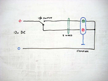
For a two aspect signal, two wires are normally required to each signal, one for each aspect with the circuit completed via the common return. With a single aspect searchlight signal using a two leg, two colour LED this can be done with two wires to each signal or even reduced to one wire per signal plus a common return using circuitry similar to the motor driven point motor. In fact for single aspect signals of this format, the circuitry required is almost identical. Once again though the diagrams are much easier to comprehend than the text.
| Two aspect signal. Coloured lamps. Two wires plus common. | Two aspect signal. Coloured lamps. One wire plus common. | Searchlight signal. Red/Green two pole LED. One wire plus common. |
 |
 |
 |
Mentioned previously in a previous article, relays are quite a useful component for use in model railways. So what are they then?
Put simply, they are electrically operated switches. Through the winding which is a coil of fine wire around a central iron core, a current is passed making the core magnetic. This attracts a hinged armature which lifts a contact or a number of contacts and performs the same function as operating a switch. When the current is disconnected the armature releases and the contacts return to the normal setting. Contact units may be make, break, changeover or make before break format, depending on the relay. Although many specifications are available the ones most useful on model railway layouts operate on 12 volts DC with contact units rated at a couple of amps.
Using circuitry, relays can be made to latch on after a push button is pressed and pressing another button can be made to release the relay. A holding circuit is provided by the relay's own make contact. Release is by either breaking the holding circuit or applying a short circuit across the relay coil. These methods are useful if the push buttons used are of the double pole single throw non locking type and are combined with the points route setting circuit. Relay contact units may also be used not only to operate signals but also to activate or isolate specified track sections. Relays can be made to be slightly slower to release by connecting a diode across the winding in reverse polarity. For a longer time delay, a capacitor may be inserted making sure that the polarity is correct. This can also help reduce arcing across the switch or push button contacts.
It is very easy for relay circuitry to become somewhat complex. That's not for here though. That would defeat the original concept of this whole series of articles, the purpose of which as stated is "Model Railway Electrics made Easy".
Some example circuits using relays are illustrated but of course there are many more variations, depending on what the requirements are.
| Non locking button, push to make operate, push to break release. | Non locking buttons, push to make operate, push to make release. |
 |
 |
With dead frog points, if contact between the switch rail and the stock rail is broken then current does not pass and all that will happen is that the train will stall on the point. This problem has now become more prevalent as on the latest issue of Peco points they now, for no explicable reason, do not have the self cleaning under rail wiper contacts fitted between the switch and stock rail. These self cleaning wipers have been in use since the days of Tri-ang and Dublo and was a well proven method of ensuring good connectivity. Whether this deletion is for manufacturing economies or as one with a cynical disposition would assume, this downgrading has been done to promote the sales of their associated accessory switches. That is for you to decide. Simply but thoroughly cleaning the contact areas will resolve the problem.
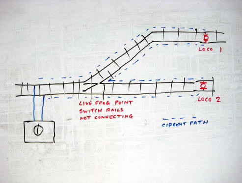
If you are using live frog points, another and possibly unexpectedly strange result occurs. If the point is fed from the toe end as normal and splits into two sidings each containing a train then under normal circumstances and as you would expect only the train on the switched track would be live. If however the contact between stock rail and the adjacent switch rail is disconnected then both trains will move simultaneously. Why does this happen? Being a live frog point, both switch rails are permanently connected to the point frog. Under this fault condition the current goes to the outer rail only, then via the train, back through the point frog, via the other train and back through the inner rail. The result being that both trains move simultaneously as they are now effectively connected in series. This is not a good situation to be in and is somewhat embarrassing, especially if you have an audience watching.
Can anything be done about it? The first and easiest solution is to make sure the location where the rails make contact is kept scrupulously clean. If that does not solve the problem then you have to resort to the complication and added expense of installing point frog switching with either an accessory switch or independent track section switches.
If you have been having unexpected collisions at your points, you now know why and what to do about it.
If you have a terminus station on your layout it is usual to provide a short isolated track section adjacent to the buffer stop to allow the isolation of a locomotive whilst another locomotive is brought on to remove the train. A simple on/off single pole switch is all that is required for the job.
Once the train has departed, the incoming locomotive is left in splendid isolation but it is all too easy to forget about it and bring in another train on top of it, with embarrassing results. So how can we alleviate the potential for making this error? Well, the simple way is to use a double pole changeover switch with the second contact unit causing a reminder lamp or LED to illuminate. This indication only reminds you that the switch is operated and the end section is isolated but not however that a locomotive is located at the end of the line
There are of course other possibilities. Using a double pole changeover switch, with this circuit the indicator is only illuminated if a locomotive is left isolated. A static locomotive presents a low impedance or resistance across the running rails and because a small lamp or ideally a LED draws very little current, this will have negligible effect on the motor. If no locomotive is present no indication is given. If the switch is operated when no locomotive is present and if you then run a train into the isolated section it will stop automatically, albeit abruptly but that is the better alternative than demolishing the buffer stop.
Once again though using our old friend common return we can save on a bit of wiring. As long as one of the rails is the common return or earth common then only a single pole changeover switch is required.
Just as a reminder, as with all common return configurations, the line controller and the indicator -12 volt supply must be derived from totally independent sources.
Check out the diagrams for the wiring solutions. As always, diagrams are much more intuitive than text can ever be. There's more dead ends next time.
| Not common
return. Double rail gap and double pole switch. |
Common
Return, Top rail common earth. Single rail gap. Single pole switch. |
|
|
|
In the terminus station it may be convenient to be able to see if the platform line is clear, if it is isolated at the end or if it is isolated at the end with a locomotive located there. This may be done by adding to the circuitry shown in the previous article.
If common return is not being employed then an extra pole on the switch is required, necessitating the use of a triple pole changeover switch. However, with the common return version, then only a double pole changeover switch, two LED's and a bit of extra wiring is required. We can now get an indication of the three possible states of the end of line section, namely clear and live, clear and isolated or occupied and isolated. A red and a yellow LED would indicate this perfectly. This though is a bit clumsy.
It would really be ideal to provide only a single multi colour LED showing either a green, a yellow or a red depending on the situation at the time. This time a three leg LED is required. One positive leg is connected to the red, another to the green and the centre one is common to the other negative side of both. The useful bit here is that if the red and green are energised simultaneously the LED glows yellow. Two series resistors are used to maintain the luminosity of the LED in all operating colours. Two ordinary diodes are also required to separate the red and green circuits. This time a three pole changeover switch is required if no common return is available but if we do revert to our old friend common return then only a two pole changeover switch is required. Now you have full indication of the state of the isolating section at the end of the siding. Green is clear and live, red is clear and isolated and yellow is occupied and isolated.
Just as a reminder, as with all common return configurations, the line controller and the indicator -12 volt supply must be derived from totally independent sources.
|
Not common return. |
Common Return, Top rail
common earth. |
|
|
|
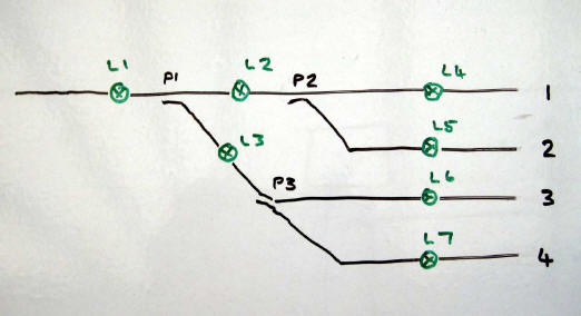
If you have a group of points at the approach to a station or yard then it would be very convenient if you could have some kind of display confirming that a complete continuous route has been set up correctly. Also, if no route is complete then conversely, the display remains darkened.
Whilst it is quite simple to have a points accessory switch connected to two lamps or LED's to indicate whether a point is in the set or normal position, this would only indicated the setting of that one individual point, not that a complete route is set. If the track layout consists of a series of points in cascade such as you would have approaching a number of sidings in a yard, then wiring through all the accessory switches in the correct sequence is all that is required. If it is deemed merited then extra intermediate lamps or LED's can be wired and installed on the display panel between the points to give a more comprehensive display. There is one serious limitation to the principal of this type of circuit though. If there is more than one approach track or duplicate routes leading to the sidings then this simple bit of circuitry does not work. In this instance some slightly more involved circuitry will be required to maintain the original concept that nothing is illuminated until a complete route is set up. That's for later.
| Panel Display. | Circuit Wiring Diagram. |
|
|
|
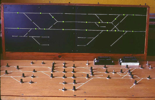
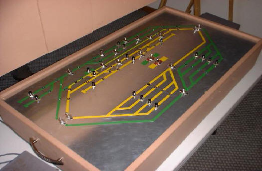
Having a visual route indicator can be very useful to a layout operator. As you will now have come to expect there is no single correct way of achieving this. There are two fundamental choices. One is to have a stand alone panel as an overlay to the control panel and the other is the integration of the point control switches, the sections switches and the illuminated display on a single panel. It's all down to personal preference.
The first method is illustrated by showing a previous Eastbank MRC H0 scale Amtrak layout, Pennsburg. This had the route display panel added on to it after the layout became operational and was located behind the main control panel. The other illustration show the integrated method as is used on the South African Railways H0 layout Magersfontein. Although the wiring or in modern parlance, programming, is entirely different the principal behind the design of the circuitry is always the same. Remember that every track formation has to be designed individually.
Which system is best? There is no easy answer to that question. It depends entirely on your own opinion or even if you would find that a route display panel would even be a useful adornment to your layout.
How is it wired? That's the next exciting episode.
| Pennsburg. Separate Control Panel and Route Display. |
Magersfontein. Integrated Control Panel and Route Display. |
|
|
|
As with point route setting circuitry there is no single standard circuitry for route displays since just as on real railways each schematic display panel has to be individually designed specifically for the group of points that they display. No matter what the track layout is though, this principal is standard and applies to any track configuration. Be warned though that if there are a large number of points then consequently the circuitry does become rather involved.
The requirements for this system are to have two change over contact units for each point. This can be provided using either a double pole change over unit accessory switch per point or to reduce the wiring between the layout and control panel, a relay connected to a single accessory switch on each point is all that is required. If using relays only for the route display they require two change over contact units. Using a relay with four change over contact units allows for the provision of switching of the track power and the controlling of associated signals.
The principal of this system is that one set of contact units per point is wired just as the way the points are arranged. At the approach end the other set of contact units are wired as a mirror image of the track layout and the two sets are then connected. At the mirror image end of the circuit all ends are connected to the earth common and on the display panel end each location where an indication is required is connected to a lamp or LED with a resistor which is then connected to the 12 volt DC supply. This can be either positive or negative 12 volts but obviously if using LED's, these must be connected with the correct polarity.
For this type of installation a wiring diagram is absolutely essential. Points should be numbered, allocated a normal and set position and all the indicators numbered too. Following the plan logically and methodically is essential to avoid errors.
Is this all a bit confusing? If there is one instance where diagrams can explain things better that text then this is it. An additional feature is that as you would expect, once the power is turned off the display darkens. However when the power is restored, the panel will indicate the true setting of the routes even if any of the points have been changed manually. A simple track plan is illustrated along with the wiring diagram but you can work out that if there is no through route then none of the indicators will light up.
There you are, you now have a display just like in a real signal box.
| Panel Display. | Circuit Wiring Diagram. |
 |
|
If you have a number of manually switched track block sections it is quite easy to get confused and allocate adjacent sections to the two different line controllers. This results in some embarrassing derailments and sometimes the tripping of the overload on the power supplies.
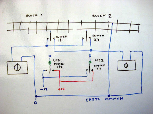
Many layouts have two line controllers and these are usually arranged so that any block section can be allocated to either controller. As illustrated in a previous article the block sections can be allocated to either the upper or lower link which can then be allocated to either line controller. This allows, with two switch movements only, to change over line controllers very quickly.
As in the illustration previously the regular LED's are connected to the -12 volt supply. If instead a two leg two colour LED is used and it is connected to either the -12 volt or +12 volt supply via a two pole centre off block section switch then this LED can either indicate green or yellow depending on which line controller the block is connected to. If route display is not being employed then the layout side of the LED is simply connected to the common earth connection. If the 0 volts common side of the LED is connected to the route display then the LED will only be lit if a valid route is set up through that block section.
This way you will not get mixed up over which line controller is controlling which block section.
Sometimes it occurs that there is a loss of continuity or even a restive joint on a layout resulting in the trains either stopping or running slower than usual. There are number of ways to locate the problem but some are more foolproof than others.
Most people will have a multi meter in their possession. These devices measure either volts, amps or ohms. They are relatively inexpensive. Readouts can either be by a moving needle or by a digital display.
One way of checking continuity is to turn on the line controller, set the multi meter to the volts scale and measure the voltage across the track. Whilst this is an adequate method to check for broken continuity, if the fault is of a resistive nature, this can lead to a false indication being displayed on the meter. Why is this the case?
When the normal 12 volts is applied across the track, the train moves at the normal speed. The dynamic resistance or impedance of the electric motor in the locomotive is fairly small and under normal conditions, all the supply voltage is available across the motor. If however there is a few ohms of resistance in series with the motor because of a resistive rail joint then a proportion of the voltage will be dropped across this resistance with the remaining across the motor. If the resistive rail joint is about equal in value to the impedance of the motor then about half the voltage is dropped across the faulty joint and the other half across the motor resulting in some slow running.
By their construction a voltmeter is of relatively high internal resistance requiring only a very small current to deflect the meter. If the resistive fault is fairly small then there is very little current flow resulting in minimal voltage drop across the faulty rail joint. The meter indicates a normal supply reading. This result is really of no use to finding the fault.
So what's the best way to find resistive track joints then? Track continuity testers are available that use an LED as indicators of continuity and polarity. However if the resistance fault is of a fairly low value then the difference in the intensity of the illumination of the LED is difficult to perceive. Ideally we require a device that will draw a reasonable current, similar to that of a locomotive. Returning to the motto of keeping it simple, that is exactly the right solution in this situation. Even better, no high tech, expensive or complicated electronic device is required. A simple 12 volt incandescent test lamp is absolutely perfect for this job. These 12 volt test lamps are available from model railway electrics suppliers and fortunately for us, they are not expensive. Treat yourself to one as soon as possible, it's one of the most useful pieces of test equipment you will ever purchase.
One feature that can enhance a model railway is operating signals. Signals today are mostly colour light power signals but in a few areas the older semaphore signals still exist. For now we shall deal with multi aspect power signals.
There is one drawback however with functioning signals on a model railway layout. Signal control really does not scale down. If absolute accuracy is required you need just as much circuitry as the real railway and probably a signal box and relay room as well to house all the necessary equipment. Don't panic though, there are a number of short cuts available to you if you are willing to compromise. For safety and for fail safe reasons real railway signalling is fully interlocked with the points and conflicting routes are automatically blocked. For model railways or train sets though this may be dispensed with.
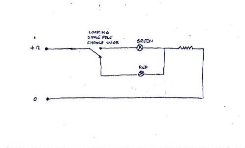
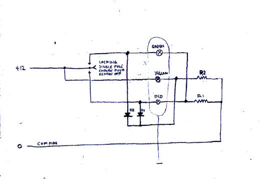
For now we will just have the signals operated independently by a single pole locking changeover switch. The simplest is a two aspect red/green signal and this is controlled with a single pole locking changeover switch. For a three aspect signal we need a single pole locking change over switch with a centre off position. A bit more wiring is required for this but as usual the diagram is easier to understand.
With the switch in the down position the red aspect is lit and current flows via diode D1 and shorts out resistor R2 thus preventing the yellow aspect illuminating. Placing the switch in the centre position extinguishes the red aspect and removes the short across R2 and the yellow aspect illuminates. Putting the switch in the upper position lights the green aspect and current via diode D2 shorts out R2 again and the yellow aspect darkens.
This circuit is polarity dependent and must be wired up as illustrated. It will not work properly with an AC supply. There are of course other ways to control signals but that's for later.
|
Two Aspect Signal. Single pole change over switch. |
Three Aspect Signal. Single pole changeover centre off switch. |
|
|
|
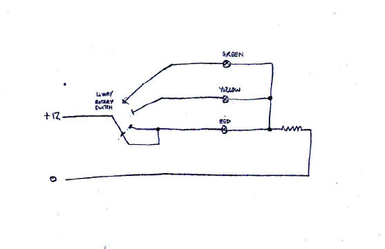
An alternative way to directly control multi aspect colour light signals is to use rotary switches. The most useful ones for us have one input to four positions and often have three separate sets of contacts. Some contact sets are non bridging and some are bridging. In this circumstance the difference is not that important. Only one set of contacts is needed for the signal.
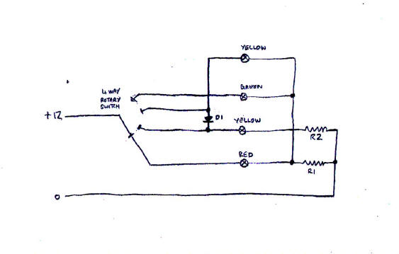
Position one is for red, position two is for yellow and position three is for green. If four aspects are required position one is for red, position two is for yellow, position three is for double yellow and position four is for green. The four aspect signal requires a bit more circuitry as either a single or double yellow aspect has to be able to be displayed and a diode and an extra resistor are required for the second yellow aspect. As always the diagrams make so much simpler to understand. Once again since there is a diode used in the circuit the polarity is important and the circuit will not function correctly on an AC supply.
The other contact unit may be used to provide power to appropriate track sections if required.
|
Multi Aspect Signal. Three Aspect. |
Multi Aspect Signal. Four Aspect. |
|
|
|
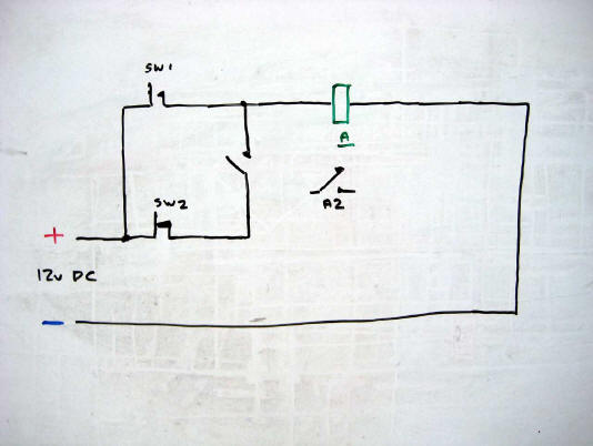
Before going on to the involvement of relays in our combined points and signals circuits there is something that really needs to be clarified. Relays are operated by applying a voltage across the winding or coil. Provided there is sufficient voltage, relays may be operated in a series or parallel configuration. However, relays may be released by at least two different methods, namely disconnecting the applied voltage across the winding or applying a short circuit across the winding but first of all ensuring of course that does not involve shorting out the power supply. The principal of this procedure is shown in the illustration.
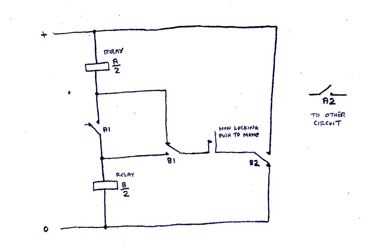
The purpose of this circuit is to use a single pole non locking switch or push button to operate a relay on its first momentary operation and release and to restore the relay on the second operation and release of the switch. Sounds simple doesn't it? If you want a challenge, you have the specification, go and try and design a circuit yourself to do this before looking at a solution as illustrated. It may even get you interested in designing model railway electric circuits yourself.
To explain the sequence of events: On the first operation of the switch relay A operates. On release of the switch relay B operates in series with relay A. Both relay A and relay B remain operated. On the next operation of the switch relay A is shorted out but relay B remains operated. On the release of the switch relay B now releases and the circuit is restored to normal and ready to repeat the procedure.
It may not seem much of a useful circuit for now but the principals of operation and release of relays may be adapted for use in more complex circuits.
|
|
In some situations it may be desirable to switch on or off a circuit or device from more than one location. This scenario exists in many houses already. If you have a long hallway or a set of stairs it is convenient to be able to switch on the light at ground level, ascend the stairs and switch off the light at the top and also of course, vice versa.
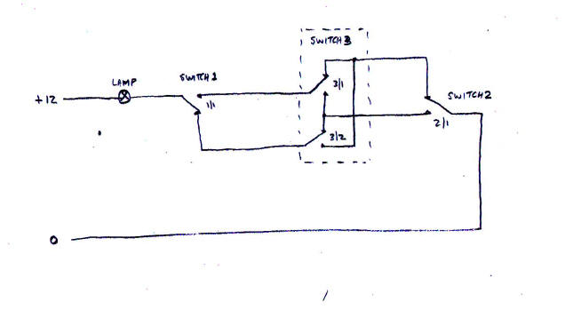
There are normally two switches used in this situation and they are of the locking, single pole, changeover type. Replicating this for use on a model railway is quite simple as shown in the diagram but there is one drawback, you can only have two separate switch locations. Can we have more than two? Of course we can.
For the intermediate switches a different type of switch is required, a locking, two pole changeover switch. The intermediate switches are wired as shown and simply reverse the two wires change off to on or on to off. There is no limit to the number of intermediate switches you can have but remember that the full current of the device you are switching travels the full length of the circuit and if this current is substantial there will be some voltage drop around this circuit. If this is going to be a problem is there an alternative? Once again the answer is yes. That's for next time.
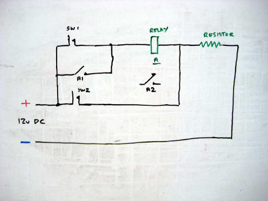
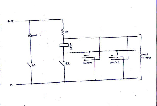
This time we are back to our old friend the relay to provide a means of switching a relatively high current without the limitations of significant voltage drop over a long distance as in Short Circuits No. 28. This time all the switches are of the non locking, centre off changeover type and there is no real limit on how many different switch locations you can have.
Operating any switch one way operates the relay in series with the resistor and this relay remains operated on the release of the switch via one of its own contact units. Another contact unit on the relay switches on the device. A lamp is shown for simplicity. When the switch is operated the other way, this applies a short circuit across the relay coil causing the relay to release and disconnect the lamp. Simples!
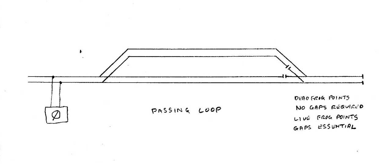
One of the most common track configurations found on a layout is the simple passing loop. Power to the track may be supplied from one end of the loop or if it is part of a continuous run oval, both ends.
As points are self isolating, trains will be isolated only if both points of the loop are set against the train. If one point is set to one line and the other set to the other line then both lines of the loop will be live, not really an ideal situation.
A further problem arises if live frog points are used. If both points are changed simultaneously everything works fine but if one point is set to one line and the other set to the other line a short circuit will occur and nothing will work. How do we overcome this limitation? By the use of two essential insulated rail gaps.
One solution is to insert two insulated rail gaps adjacent to the point frog at the point further away from the power feed. Even if one point is set against the other, no short circuit occurs.
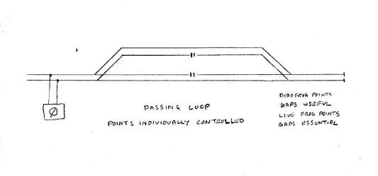
As always, there is an alternative. If the gaps are relocated, still on the inner rails, to a position in the centre of the loop some extra operational opportunities result. With each point individually operated, the point's self isolating feature isolates the section the point is switched away from. It is of course essential that trains do not over run the gap as if it does and the point at the far end is set against it, a short circuit will occur. Although gaps are not essential for dead frog points, inserting insulated gaps as shown results in the same operating flexibility.
|
|
|
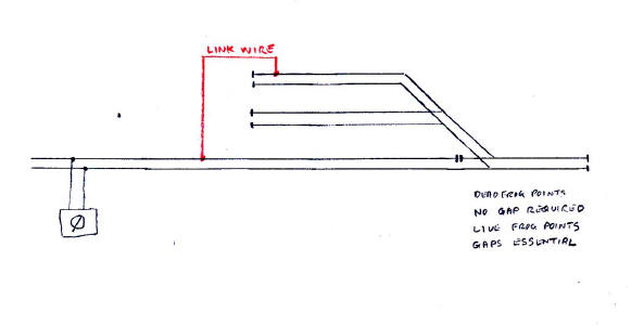
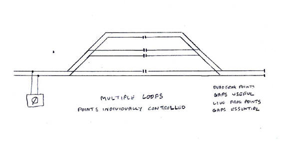
Another track situation often found is where a single line approaches a number of loops and back into a single line. This can lead to a great deal of wiring if misleading advice is followed. Can it be done without any additional wiring? Well, yes, of course it can.
By utilising our old friend the insulated rail gap located as shown the flexibility of being able to store and isolate two trains on each loop becomes possible. With gaps so located, this arrangement works equally well with dead or live frog points. There is no limitation as to how many loops may be installed, just that the intermediate loops are gaped on both rails as shown. The one limitation is that the routes at each end of the loops must be able to be controlled individually. Look, no wires!
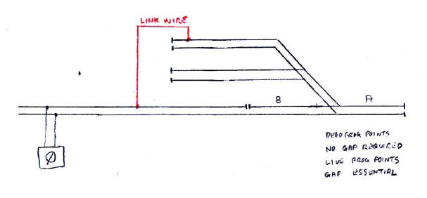
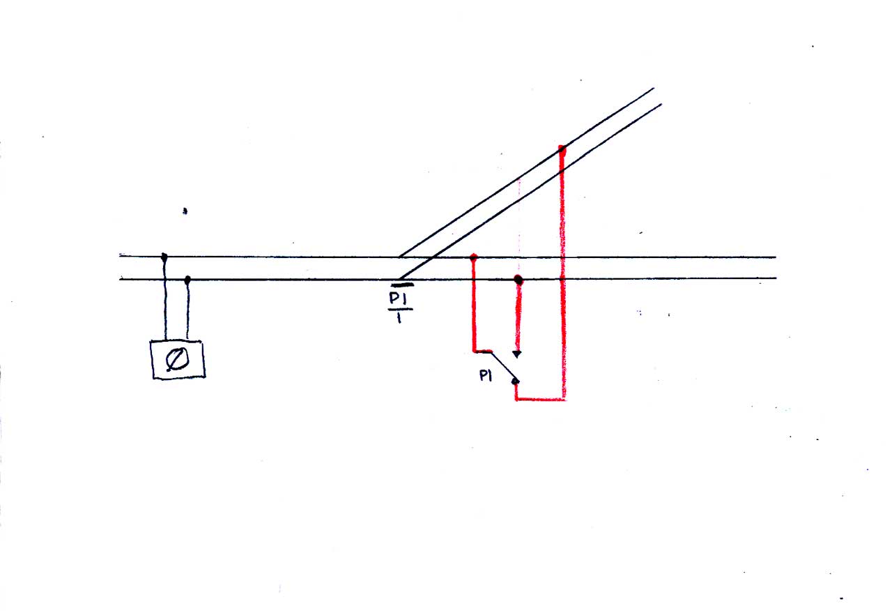
It is usually good practice to apply the power feed at the toe end of points. Sometimes a situation can occur where this is not practical and a solution often offered is to create an additional track section and switched track feed at the toe end of the furthest away point.
It can be done in a much simpler way though, automatically and without any switches being required. All that is needed for dead frog points is a fixed link wire and for live frog points, a fixed link wire and one insulated rail gap.
For a bit of extra flexibility of operation the gap may be relocated about a loco length before the point. When the point next to A is set towards the sidings, this allows one loco to be isolated at position B whilst another loco has full access from position A to all the sidings all without any additional switching or wiring. This arrangement applies equally to both to dead or live frog points.
|
|
|
Frog switching of live frog points was until recently a relatively uncommon situation and was only normally found with kit or hand built points. It has now become much more common due to Peco making a retrograde modification to their range of turnouts or points. What was this downgrade? Up until recently all points were fitted with under rail wiper contacts on the switch rails which engaged when in contact with their associated stock rail. The sliding movement meant that these contacts were self cleaning and greatly assisted contact. Alas, these wiper contacts have been omitted from the recent range of Peco points. Contact now relies only on the switch rail pressing against the stock rail. As no sliding takes place this means of contact is prone to intermittent resistive or complete loss of electrical conductivity. Peco of course recommend that you install frog switching circuitry but they would do, wouldn't they.
Now the more cynical amongst you will question why Peco have downgraded their product. Is it to sell more Peco accessory contact switching units? Your decision!
Anyway, frog switching is not difficult. What is required is a change over contact unit which operates simultaneously with the point. An accessory switch fitted to the point motor is the most simple but other methods may be used. With motor driven systems a change over accessory change over contact on the motor unit may be used. Alternative electronic units are available but the object here is to keep everything simple.
It is advisable to ensure operation of the point and frog switching is synchronised. The wiring is quite straightforward. The lever contact of the changeover switch is connected to the rails adjacent to the frog and the make and break contacts are connected to the stock rails as shown. Remember that both rails adjacent to the live frog are permanently in contact. The point and change over switch are shown in the straight on position. As usual the diagram is easier to follow than the text.
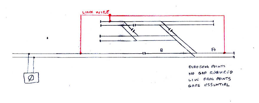
The track layout shown in Short Circuits No. 33 although practical, has a limited amount of operating potential. With the addition of a further three points the flexibility of operation becomes more enhanced.
For live frog points the two link wires and all the gaps are essential. For dead frog points only the two link wires are essential. The gap to the left of B is useful if the isolation of a loco on the main line is required. Points may be changed individually or grouped using method shown in previous articles.
A feature that can enhance model passenger carriages is interior lighting, especially in a reduced lighting environment. Interior lighting is not a recent addition as it was offered by Trix and later by Tri-ang Hornby with their Mk. 2 Brake First Corridor and Tourist Second Open passenger cars. These vehicles had two interior light bulbs and pickup was by wipers on all the axles.
There is however a couple of problems with this system on conventional DC layouts. One is that the track voltage and therefore the train speed must be reasonable high for the lights to glow and the incandescent lamps do tend to draw quite a bit of power especially on longer trains. Can we improve on this situation? Of course we can.
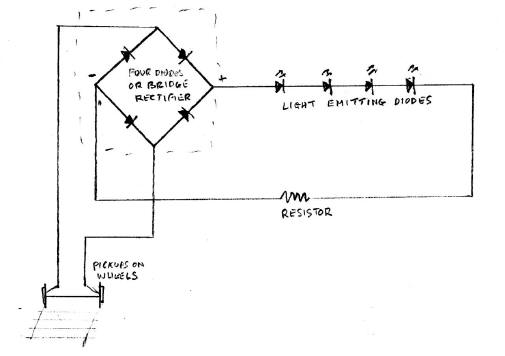
The solution is to use white or warm white Light Emitting Diodes or LED's. These devices require much less current to operate and will operate on a greater range of voltages, meaning that they will glow just after the train starts to move. A number of LED's may be connected in series within the carriage but a limiting resistor is also required to be inserted in series with the LED's. However we now have another problem. The word diode is the clue. These devices only emit light when the current passes in one direction only. In the reverse direction they do not operate. If lighting is only required in one direction it is good practice to insert a normal diode in the circuit to prevent damage by reverse voltages. Lighting in one direction is not really what we want though, is it?
For the lighting to operate in both directions a set of four regular diodes or a small bridge rectifier is necessary. Which to use depends on available space within the passenger car. The rectifier ensures that the current is always presented to the LED's in a uniform direction no matter the direction of the train. Of course when the train stops, all the lights go off. There are ways of overcoming this situation but that is really out with this series as they are certainly not basic nor simple.
However if you have overhead catenary on the layout and are using electric locomotives which collect power from functioning pantographs, a solution is to run the locomotive off the overhead and apply a constant DC supply to the track to illuminate the passenger cars. This method uses a common return configuration. See previous articles for how this can be done.
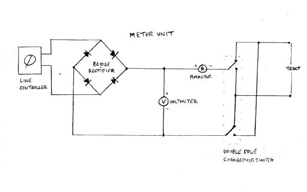
It can at times be of benefit to be able to monitor the performance of your locomotives. A simple way to do this is to install a meter unit containing a voltmeter and an ammeter. The voltmeter indicates the track voltage and the ammeter indicates the current drawn by the locomotive.
Unfortunately commercially made ready to use units are not readily available. Fear not however, a meter unit is not difficult to make yourself. The voltmeter is wired across the track supply and the ammeter is wired in series with the track feed. Yet again the diagram shows how simple it is to construct.
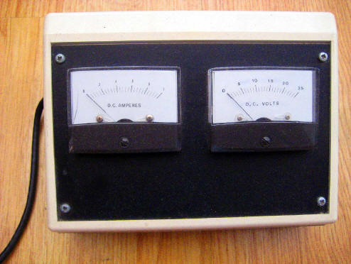
Meters with a digital readout are available but just how useful these are with rapidly changing voltage and current values is questionable. For 00, H0 and N scale, analogue moving coil meters reading zero to twenty or twenty five volts and zero to one or two amps are really more useful in this circumstance. With larger scales, voltage and current levels will be greater. For aesthetic reasons it is better if both meters are of the same physical dimensions.
The more astute amongst you will have noticed a slight, well major drawback with this description so far. It only works properly with one direction of travel of the train!
One solution is to modify the line controller and insert the voltmeter and ammeter before the reversing switch. This method is not really to be recommended and will of course invalidate any warranty of the unit. It can be done another way without resorting to this drastic action and invalidating any warranty.
By inserting a bridge rectifier between the line controller output and the meter unit, this will ensure that the voltage and current is always applied in the same direction. As the reversing switch on the line controller now has no effect and has become redundant, another double pole changeover reversing switch must be inserted on the meter unit after the meters towards the track to allow for operation in the reverse direction. A slight inconvenience but it is better than modifying the line controller.
So what do the two meters indicate? The voltmeter generally advances along with speed. If the voltmeter suddenly indicates a high value and the ammeter indicates zero there is a disconnection. The ammeter should indicate a reasonable smooth transition of current levels. If the indicator stutters whilst the train is in operation, this may be a sign of an intermittent contact. If the voltmeter indicates a low value and the ammeter a high value, there is an overload or short circuit. This is by no means a definitive list of scenarios that may occur.
There is no ideal or correct meter reading value. Older models by Hornby Dublo and Wrenn and also Tri-ang Railways and Tri-ang Hornby generally draw more current than recently manufactured models. This is not necessarily indicating any fault condition, that is how they were designed to operate. Even models of similar manufacture may indicate different readings.
|
|
|
Not everyone will have the inclination to go to the effort and expense of constructing a dedicated meter unit especially if it is considered that it will not see much use. The alternative is to purchase a multimeter. Modern items are not expensive. Two distinct types are on offer, one with an analogue moving coil indicator and the other with a digital readout. You pay your money and you take your choice.
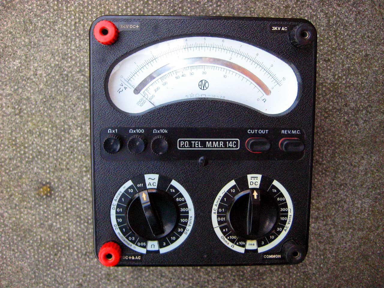 |
The title "Multi" offers a clue. These devices may be used to measure AC or DC voltage (Volts), AC or DC current (Amps) and also resistance (Ohms) but not all at the same time of course. If you are not sure what value you are measuring set the selector to the highest possible range. On setting the Multimeter to read voltage it is then connected across the track supply. If the reading is negative, reverse either the track supply or the leads to the Multimeter. To measure current, set the selector to the appropriate current range and connect in series with the track supply. Either track feed wire will suffice. Again, if the reading is negative, reverse the leads to the Multimeter. To measure resistance, first make sure all power is disconnected from what you wish to test. This is not just gratuitous advice, this is absolutely mandatory. If a circuit is live, this could lead to damage to the Multimeter and even worse, possibly to you. The Multimeter has a battery within and this provides power to measure resistance and continuity. If you don't have a resistor colour code, this is a useful way of finding out a resistor's value. The resistor colour code is available in many books and on the internet. It may be remembered by a very politically incorrect rhyme which for obvious reasons will not be repeated here. Alternatively just ask anyone in the electronics industry, they will be able to tell you. |
| The Multimeter illustrated is an ex GPO Meter Multi Range 14C/2 Avo/80/6 and is of some vintage. Do not panic though. Modern Multimeters are less complicated, much more compact and a lot less expensive. | |
Some manufacturers now offer points or turnouts with point motors built in. One type is made by Kato in N scale but in this instance the point motor is of different configuration in that there are only two wires required to be connected to each point. To operate the point a short pulse of direct current is passed through the motor and this sets the point. To reset the point another short pulse of direct current is required but this time in the reverse direction. As you may expect there are alternative methods to achieving point operation.
The instructions as supplied with the Kato points states that the two wires be connected to a two pole, centre off, non locking change over switch. This is perfectly acceptable if there are only a few points but if there is a significant number of points this will require twice as many wires as there is points between the control panel and the layout. Is there a way to reduce the amount of wiring? Of course there is and our saviour is our old friend common return.
As is in life, you do not get something for nothing though. For the common return method a supply of power at +12v and -12v DC with reference to a common zero volt common is required. This can be derived from a single 12v AC supply using the simple circuit shown in the second diagram using two diodes and two 470 microfarad electrolytic capacitors. Capacitors must be connected with the polarity shown. For the integrity of the point motors or for anything else for that matter, do not connect anything between the +12v and -12v wires as the difference in potential is of course 24 volts.
|
Double pole, non locking, centre off switch. Two wires per point. |
Single pole, non locking, centre off switch. One wire per point plus one single common return wire. |
|
|
|
Insulated rail gaps in practice.
As we have seen in previous articles, the rail gaps that are essential with live frog points have been indicated in a number of theoretical scenarios. This time we have a practical layout to demonstrate just how simple it is to have a continuous run layout with live frog points and just five insulated gaps while still maintaining the self isolating feature of the points. The only extra wiring required is a single link wire as shown to maintain conductivity to the head shunt on the loop line. As always when operating the layout it is a good idea to set the points correctly before running over any insulated rail gaps otherwise a short circuit could occur and your train will stop abruptly. However if you wish to use dead frog points, none of the gaps are required but the link wire is still necessary. Once again the diagram should make it clear.